EQUIPOTENTIAL LINES AND FLOW DIRECTION
Example Problem 3
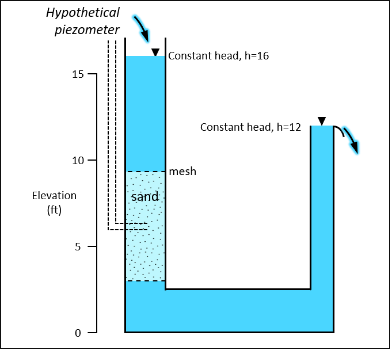
The goal of this exercise is to understand how equipotential lines are drawn in an isotropic medium and how they allow us to determine the direction of groundwater flow.
a) Draw equipotential lines in the sand at 1 ft intervals.
b) To what level will water rise in the hypothetical piezometer?
Interactive Hydraulic Head with Sand Divisions
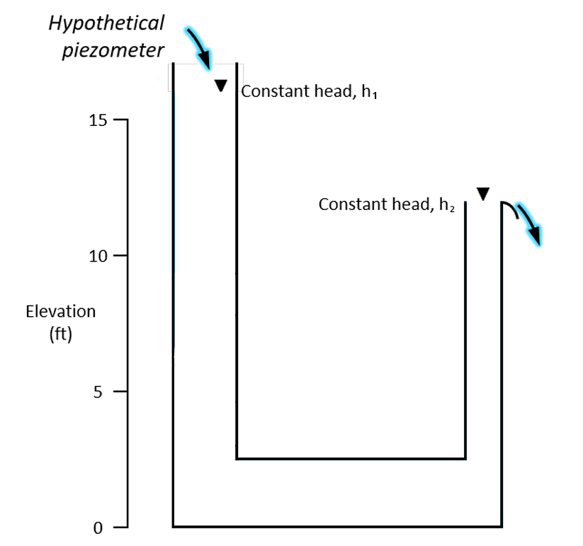
h₁ (left head): 0 ft
h₂ (right head): 12 ft
Equipotential height (piezometer): 0 ft
Default head on the right (h₂) = 12 ft.
Adding sand divisions increases the left head (h₁) by 1 ft per division.
Divisions appear only inside the sand zone.
Water level can be adjusted between 0 and 12 ft using either input type.
Show solution
Questions:
a) Draw equipotential lines in the sand at 1 ft intervals.
b) To what level will water rise in the hypothetical piezometer?
Solutions:
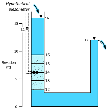
a) The constant head values at the top and bottom of the sand column are equal to the water-level elevation of the column of water that bounds each end of the porous medium. Flow must be vertical in the sand column given the geometry of the cylinder, and the potentiometric lines must be horizontal (equipotential contours are perpendicular to the direction of flow and perpendicular to no-flow boundaries). The head gradient is specified by the spacing between contour lines; in this case, they must be equally spaced because the medium is homogeneous.
b) The water level in a piezometer is equal to the hydraulic head at the point of measurement, which in this case is the open end of the piezometer in the sand. Therefore, the water level in the hypothetical piezometer is 14 ft.