5.3 Aquifers and Aquitards
This system consists of an upper clay unit (aquitard) separating an upper unconfined aquifer from a lower confined sand aquifer. Potentiometric contours connect points of equal hydraulic head and, in isotropic aquifers with predominantly horizontal flow, are approximately vertical lines. The potentiometric surface represents the level to which water would rise in a well open to the confined aquifer.
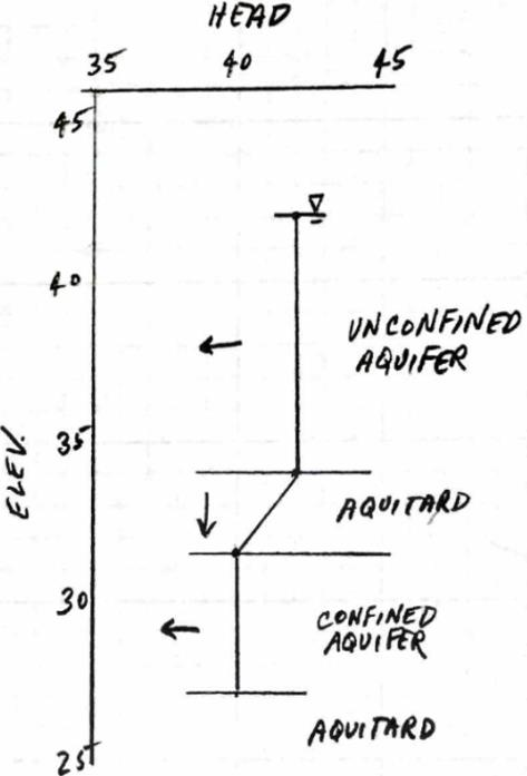
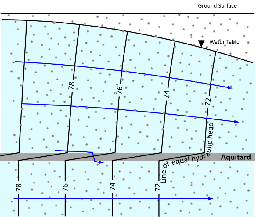 Figure 28 – Potentiometric contour lines in an unconfined and confined aquifer separated by an aquitard (Cohen and Cherry, 2020).
The flow direction through the aquitard is determined by comparing the hydraulic head above and below the low-conductivity unit. In the case of Figure 27a, the water table is above the potentiometric surface, so flow through the clay is downward (recharge).
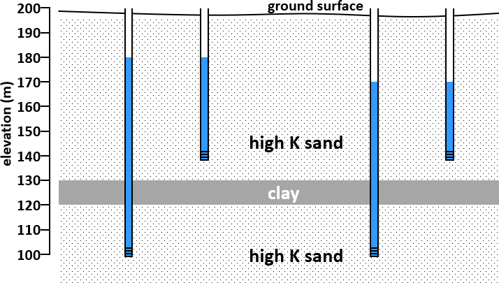
Example Problem 11
Analyze the provided hydrogeological cross-section consisting of an upper clay unit and a lower sand unit with two monitoring wells. Based on the measurements in the diagram, answer the following questions regarding groundwater flow.
Interactive exercise
Exercise 11: Groundwater Flow and Hydraulic Head
Use the canvas to sketch your answers before revealing each solution.
Parts A & B — Equipotential Contours and Potentiometric Surface
A) Draw the equipotential contours in the lower sand at 1 m intervals.
B) Trace the potentiometric surface (line connecting the water levels in the wells of the confined aquifer).
Draw on the canvas then reveal the solution
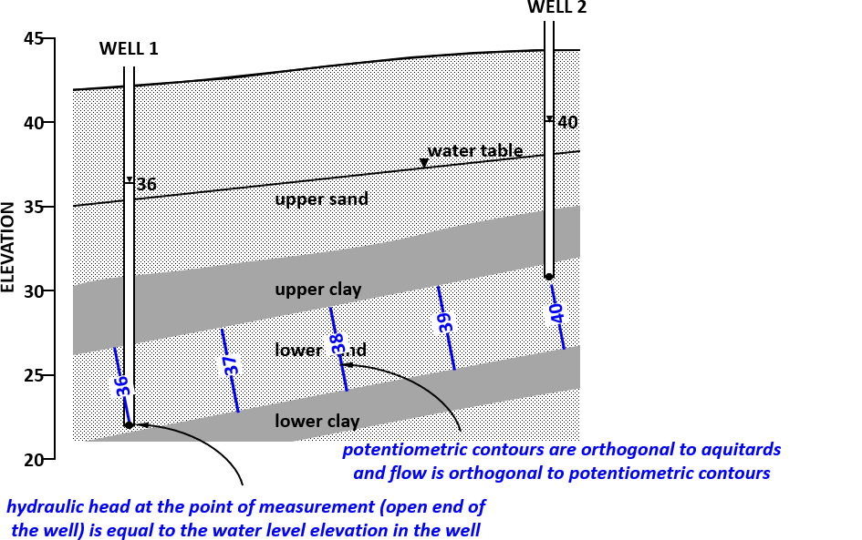
Show solution
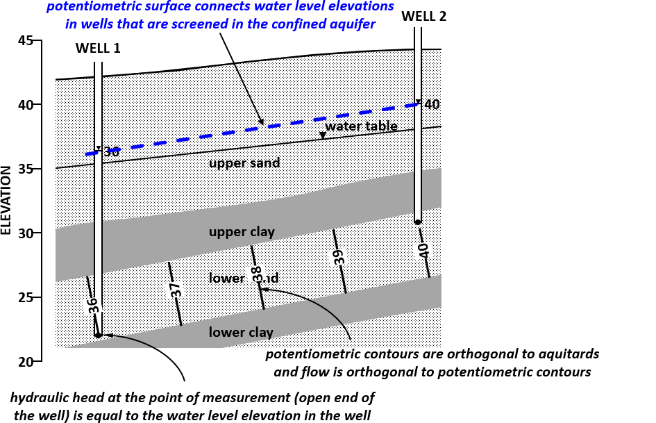
Problem 11 Solution
The step-by-step solution can be explored in the interactive exercise above. The key takeaways are:
- Potentiometric contours in the lower sand unit are evenly spaced vertical lines based on the linear interpolation of head values between the wells, decreasing from left to right.
- The potentiometric surface is represented by a planar surface (a straight line in cross-section) connecting the head elevations of the two wells.
- The direction of groundwater flow through the upper clay unit is mainly downward (recharge). This is determined by comparing the water table elevation to the potentiometric surface elevation. Since the water table is higher, there is a downward vertical gradient.
- The expected vertical hydraulic head profile near Well 2 shows a relatively steep downward gradient through the clay, followed by a relatively constant head (or a much slighter gradient) through the highly conductive sand.